-

OSU键盘小幅度升级 2019-1-7
之前的那个键盘因为用的鼠标主控(见http://blog.readgroup.cn/post/40),会和数位板产生冲突,禁掉鼠标按键的话使用上又不方便,所以就还是换键盘的主控吧。本来想用digispark做主控的,但是延迟啥的没处理好,这个方案以后再说吧。目前用digispark来控制LED呼吸灯。 成品如图: 接口上也改为了microusb接口,更加方便携带。所有焊接处都用热熔胶封死,不小心漏了,导致有点多了。 键盘主控如图: 只焊接了ZX两个按键,打OSU足够了。
-

树莓派上搭建网站监测面板 2018-12-27
因为需要实时了解服务器状态,所以需要一个能够查看服务器在线状态的软件。找了几个,效果都不太行,不如用网页版的,还方便。最终选择了Server Monitor,下载地址:http://www.phpservermonitor.org。 环境要求就基本的php就行了,需要数据库以及cURL扩展。安装没啥问题,跟着步骤走就行。刚开始可能遇到配置文件无法写入的情况,手动把配置文件内容复制过去即可。同时config.php.sample改为config.php,保存再回到安装界面点击继续即可。安装完成登录就可以用啦。添加自己的服务器配置,一般用服务吧,检测端口比较好用。ping的功能好像不太行,试了几次没作用,暂时没找到原因。 然后要注意的是设置中的刷新时间是页面的刷新时间,不是检测代码的刷新时间,设置这个还没法自动检测。这里我们就需要用到crontab定时任务了,一般Linux中都集成了。 进入编辑界面: sudo crontab -e 在最下面添加如下代码: */5 * * * * php /var/www/cron/status.cron.php 后面的路径根据实际修改。 重启crontab: sudo /etc/init.d/cron restart 之后就可以正常使用了,现在是5分钟检测一次,可以自己修改时间,具体crontab的使用可以参见相关文档。
-
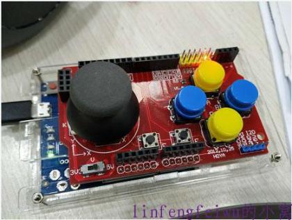
利用arduino leonardo打造游戏手柄 2018-12-21
虽然说买一个简易的手柄也就几十块钱,效果还比这个好很多,但总是想自己做一个玩玩。 所用材料: arduino leonardo板子一个, arduino mega2560外壳一个, JoyStick Shield手柄扩展板一个。 将上述物品组装在一起,如图: 接着就是能够实现手柄功能的代码: #include <Joystick.h> #define RANGE 30 Joystick_ Joystick(JOYSTICK_DEFAULT_REPORT_ID,JOYSTICK_TYPE_GAMEPAD, 7, 0, // Button Count, Hat Switch Count true, true, false, // X and Y, but no Z Axis false, false, false, // No Rx, Ry, or Rz false, false, // No rudder or throttle false, false, false); // No accelerator, brake, or steering void setup() { // Initialize Button Pins pinMode(2, INPUT_PULLUP); pinMode(3, INPUT_PULLUP); pinMode(4, INPUT_PULLUP); pinMode(5, INPUT_PULLUP); pinMode(6, INPUT_PULLUP); pinMode(7, INPUT_PULLUP); // Initialize Joystick Library Joystick.begin(); Joystick.setXAxisRange(-1, 1); Joystick.setYAxisRange(-1, 1); Serial.begin(115200); } // Last state of the buttons int lastButtonState[7] = {0,0,0,0,0,0,0}; int X,oldX; int Y,oldY; void loop() { // Read pin values for (int index = 0; index < 7; index++) { int currentButtonState = !digitalRead(index + 2); if (currentButtonState != lastButtonState[index]) { Joystick.setButton(index, currentButtonState); lastButtonState[index] = currentButtonState; } } X=analogRead(A0); Y=analogRead(A1); if ((X!=oldX) || (Y!=oldY)) { if ((X>=512-RANGE) && (X<=512+RANGE)) {Joystick.setXAxis(0);} else if (X>512+RANGE) {Joystick.setXAxis(-1);} else {Joystick.setXAxis(1);} if ((Y>=512-RANGE)&&(Y<=512+RANGE)) {Joystick.setYAxis(0);} else if (Y>512+RANGE) {Joystick.setYAxis(-1);} else {Joystick.setYAxis(1);} oldX=X; oldY=Y; } delay(10); } 所用到的库文件:https://github.com/MHeironimus/ArduinoJoystickLibrary 其中有些参数可以根据需要酌情修改。 扩展版引脚定义: X值接A0口 Y值接A1口 A接D2 B接D3 C接D5 D接D4 E接D6 F接D7 下载完程序,连上电脑就能识别成一个手柄了,但现在还没有按键映射,这里还需要另一个工具Xpadder(点击下载),利用这个来完成按键的映射。推荐使用提供的这个老版本,功能够用操作简单,新版在win10上好像有点问题。软件使用很简单,新建配置文件和映射文件即可。 最后一切搞定,来吧小时候的魂斗罗~ 参考连接: https://www.arduino.cn/thread-46192-1-2.html https://www.jianshu.com/p/9fc765524050
-
利用树莓派远程唤醒主机 2018-11-5
之前抽奖得到一个向日葵的开机棒,可以用来远程开机,后来不知道啥原因不好使了,就想到利用树莓派来远程开机,反正树莓派24小时一直不关。我这里的树莓派是安装了树莓派系统的台式机,不过方法是通用的。 首先开启主板的网卡唤醒功能(注意把本地硬盘的启动顺序放第一,不要把网卡放第一,不然会起不来),查到自己电脑的mac地址,这个很简单就不说了。 ssh登陆树莓派,安装etherwake: apt-get install etherwake 安装完成拿另一台局域网的主机登陆树莓派测试一下: etherwake MAC地址(xx:xx:xx:xx:xx:xx) 正常的话不会有任何报错,并且主机也启动了。到这一步如果树莓派能够外网访问的话直接用ssh登陆下开一下就好了,后面的可以不弄,但是为了方便,下一步开始我配置了网页shell命令的方式来快速执行指令。 使用https://github.com/b374k/b374k这一php工具,把它放在服务器上,第一次使用的时候需要自定义生成一个文件,根据页面提示选择模块,我们这里不需要别的模块,可以都不要,然后设置密码后点击pack后就生成了一个b374k.php文件。然后把除了这个文件外的别的文件都删除,以免带来隐患。(注意,这个文件可操作性较高,请一定重命名文件和设置高强度密码) 然后在相同目录新建一个wake.sh脚本: #!/bin/sh sudo etherwake MAC地址 echo "已执行远程开机命令" 给与777权限。然后查看下网页端执行shell命令的用户是谁,我们要给它一个免输密码权限,不然无法执行需要root权限的脚本。在ssh中输入以下命令: lsof -i:80 找到自己网页服务的名称,我用的是lighttpd,对应的用户为www-data。 接下来给www-data免密码执行脚本权限: nano /etc/sudoers 添加以下语句: www-data ALL = NOPASSWD: ALL 然后重启服务器。 之后网页访问相应文件,输入密码,在命令行输入./wake.sh回车即可,看到提示即表明命令发送成功。我是使用的frp加443端口来外网访问的,这样安全性要好一点。 至此,利用树莓派来远程开机就实现了。并且,这样一来就可以开启局域网内任意一台主机了,相比向日葵局域网版,成本可以说大大降低,因为用nanopineo的话总共硬件才几十块钱。
-

安装office2016报错的经历 2018-10-18
给女朋友的电脑重装office,电脑是win7的系统,结果安装到一半就开始报错没有任何错误代码,然后就显示"Microsoft setup Bootstrapper已停止工作",根据网上的方法绕了一圈也没弄好。 但后来发现,系统服务(运行services.msc)中Task Scheduler没有启动,手动也开启不了,就怀疑和这个有关。然后找到一个指令,在cmd中执行:netsh winsock reset 之后重启,发现服务可用了,再安装office就一切正常了!
-

显示本学期第几周php 2018-10-3
有时候需要知道现在是本学期的第几周,但又不方便算,所以一个小的php代码解决这个问题。 代码: <?php header("Content-Type: text/html;charset=utf-8"); //可不要,在这里只是为了让确定字符格式,防止乱码。 $week = date('W'); $zhou = $week-35; //这里要自己算一下当前是第几周,再减去差值,如果差值为0则显示的就是今年的第几周 $weekarray=array("日","一","二","三","四","五","六"); //先定义一个数组 ?> <html> <title><?php echo '第'.$zhou.'周'; echo "星期".$weekarray[date("w")]; ?> </title> <center><h1><?php echo '今天是2018-2019第一学期的第'.$zhou.'周'; ?> <br> <?php echo "星期".$weekarray[date("w")]; ?> </h1></center> </html> 美化版: <?php header("Content-Type: text/html;charset=utf-8"); //可不要,在这里只是为了让确定字符格式,防止乱码。 $week = date('W'); $zhou = $week-35; //这里要自己算一下当前是第几周,再减去差值,如果差值为0则显示的就是今年的第几周 $weekarray=array("日","一","二","三","四","五","六"); //先定义一个数组 ?> <html> <title><?php echo '第'.$zhou.'周'; echo "星期".$weekarray[date("w")]; ?> </title> <center><h1> 今天是2018-2019第一学期的第<span style="color: rgb(112, 48, 160);"><strong><span style="font-size: 200px;"><?php echo $zhou; ?></span></strong></span>周 <br> 星期<span style="color: rgb(112, 48, 160);"><strong><span style="font-size: 180px;"><?php echo $weekarray[date("w")]; ?></span></strong></span> </h1></center> </html>
-
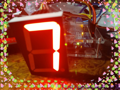
只能显示星期的数码管时钟 2018-8-5
这个东西完全是突发奇想,有时候就只想看下今天星期几,离周末还有几天。。。 先上效果图: 硬件上用的是一个共阴的1.5寸数码管,根据官方引脚资料(下图)接上UNO。 把A至G分别接在D2至D9,1、5接在GND上。 然后再接上DS3231模块,用法及库文件见:http://blog.readgroup.cn/post/61 代码: #include <Wire.h> #include "ds3231_2.h" #define BUFF_MAX 128 uint8_t time[8]; char recv[BUFF_MAX]; unsigned int recv_size = 0; unsigned long prev, interval = 1000; int pinDigitron = 2; //管脚D2连接到数码管的A脚,D3连B... D9连h void setup() { Serial.begin(9600); Wire.begin(); DS3231_init(DS3231_INTCN); memset(recv, 0, BUFF_MAX); Serial.println("GET time"); for(int x=0; x<8; x++) pinMode(pinDigitron+x, OUTPUT); //设置各脚为输出状态 } //在数码管中显示数字的函数 void displayDigit(unsigned char digit) { //定义一个数组表:不同数字的abcdefgh各段的取值 unsigned char abcdefgh[][8] = { {1,1,1,1,1,1,0,0}, //0 {0,1,1,0,0,0,0,0}, //1 {1,1,0,1,1,0,1,0}, //2 {1,1,1,1,0,0,1,0}, //3 {0,1,1,0,0,1,1,0}, //4 {1,0,1,1,0,1,1,0}, //5 {1,0,1,1,1,1,1,0}, //6 {1,1,1,0,0,0,0,0}, //7 }; if ( digit >= 16 ) return; for (unsigned char x=0; x<8; x++) digitalWrite( pinDigitron + x, abcdefgh[digit][x] ); } void loop() { char in; char buff[BUFF_MAX]; unsigned long now = millis(); struct ts t; // show time once in a while if ((now - prev > interval) && (Serial.available() <= 0)) { DS3231_get(&t); //Get time displayDigit(t.wday); //调用displayDigit()子函数,显示数字 prev = now; } }
-
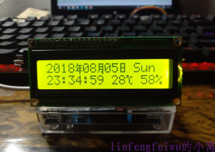
ESP8266+1602时钟(温湿度版) 2018-8-5
上一个时钟只能显示时间,这次的这个又增加了温湿度,功能上更加完善。1602也改为了IIC的,方便接线。温湿度传感器使用的是DHT11,如果要精度再高点可以使用DHT22,他们用的是同一个库。 硬件连接(注意GPIO标号为板子后面的标示): 1602: VCC —— VCC GND —— GND SCL —— SCL/GPIO4 SDA —— SDA/GPIO5 DHT11: VCC —— VCC GND —— GND out——GPIO12 (D1 mini接线: SCL —— D1 SDA —— D2 DHT11 out——D6) 代码: /* ESP8266+1602IIC wifi clock by: linfengfeiwu http://blog.readgroup.cn */ #include <ESP8266WiFi.h> #include <Time.h> #include <Timezone.h> #include "NTP.h" //DHT11 Sensor: #include "DHT.h" #define DHTPIN 12 // what digital pin we're connected to #define DHTTYPE DHT11 // DHT 11 DHT dht(DHTPIN, DHTTYPE); //I2C LCD: #include <Wire.h> // Comes with Arduino IDE #include <LiquidCrystal_I2C_DS3231.h> // Set the LCD I2C address #define I2C_ADDR 0x27 // Define I2C Address for the PCF8574T //---(Following are the PCF8574 pin assignments to LCD connections )---- // This are different than earlier/different I2C LCD displays #define Rs_pin 0 #define Rw_pin 1 #define En_pin 2 #define BACKLIGHT_PIN 3 #define D4_pin 4 #define D5_pin 5 #define D6_pin 6 #define D7_pin 7 #define LED_OFF 0 #define LED_ON 1 /*-----( Declare objects )-----*/ LiquidCrystal_I2C lcd(I2C_ADDR,En_pin,Rw_pin,Rs_pin,D4_pin,D5_pin,D6_pin,D7_pin); // Set your WiFi login credentials #define WIFI_SSID "xxx" // 使用时请修改为当前你的 wifi ssid #define WIFI_PASS "xxx" // 使用时请修改为当前你的 wifi 密码 #define ledPin 14 // 定义ledPin连接到GPIO14 //年 byte Nian[8] = {0b01000,0b01111,0b10010, 0b01111, 0b01010, 0b11111, 0b00010, 0b00010}; //月 byte Yue[8] = {0b01111, 0b01001, 0b01111, 0b01001, 0b01111, 0b01001, 0b10011, 0b00001}; //日 byte Ri[8] = {0b01111, 0b01001, 0b01001, 0b01111, 0b01001, 0b01001, 0b01111, 0b00000}; //摄氏度 byte du[8] = {0b11000,0b11011,0b00100, 0b00100, 0b00100, 0b00100, 0b00011, 0b00000}; // This clock is in the Mountain Time Zone // Change this for your timezone // 北京时间时区 #define STD_TIMEZONE_OFFSET +8 // Standard Time offset (-7 is mountain time) // *************************************************************** // TimeZone and Daylight Savings Time Rules // *************************************************************** // Define daylight savings time rules for the China TimeChangeRule mySTD = {"", First, Sun, Jan, 0, STD_TIMEZONE_OFFSET * 60}; Timezone myTZ(mySTD, mySTD); WiFiClient client; // This function is called once a second void updateDisplay(void) { TimeChangeRule *tcr; // Pointer to the time change rule // Read the current UTC time from the NTP provider time_t utc = now(); // Convert to local time taking DST into consideration time_t localTime = myTZ.toLocal(utc, &tcr); int hhhh = dht.readHumidity(); int tttt = dht.readTemperature(); // Map time to pixel positions int weekdays= weekday(localTime); int days = day(localTime); int months = month(localTime); int years = year(localTime); int seconds = second(localTime); int minutes = minute(localTime); int hours = hour(localTime) ; //12 hour format use : hourFormat12(localTime) isPM()/isAM() Serial.println(""); Serial.print("Current local time:"); Serial.print(days); Serial.print("/"); Serial.print(months); Serial.print("/"); Serial.print(years); Serial.print(" - "); Serial.print(hours); Serial.print(":"); Serial.print(minutes); Serial.print(":"); Serial.print(seconds); Serial.print(" - "); Serial.print(dayStr(weekdays)); Serial.println(""); lcd.clear(); lcd.setCursor(0,0); lcd.print(years); lcd.write(byte(0)); if(months<10) { lcd.print("0"); } lcd.print(months); lcd.write(byte(1)); if(days<10) { lcd.print("0"); } lcd.print(days); lcd.write(byte(2)); lcd.print(" "); printWeek(weekdays); lcd.setCursor(0,1); if(hours<10) { lcd.print("0"); } lcd.print(hours); lcd.print(":"); if(minutes<10) { lcd.print("0"); } lcd.print(minutes); lcd.print(":"); if(seconds<10) { lcd.print("0"); } lcd.print(seconds); lcd.print(" "); lcd.print(tttt); lcd.write(byte(3)); lcd.print(" "); lcd.print(hhhh); lcd.print("%"); } void setup() { Serial.begin(115200); pinMode(ledPin, OUTPUT); delay(10); lcd.begin(16, 2); // Switch on the backlight lcd.setBacklightPin(BACKLIGHT_PIN,POSITIVE); lcd.setBacklight(LED_ON); lcd.createChar(0, Nian); lcd.createChar(1, Yue); lcd.createChar(2, Ri); lcd.createChar(3, du); dht.begin(); // We start by connecting to a WiFi network initNTP(WIFI_SSID, WIFI_PASS); } // Previous seconds value time_t previousSecond = 0; void loop() { // Update the display only if time has changed if (timeStatus() != timeNotSet) { if (second() != previousSecond) { previousSecond = second(); // Update the display updateDisplay(); } } delay(1000); } void printWeek(int week) { switch(week) { case 1: lcd.print("Sun");break; case 2: lcd.print("Mon");break; case 3: lcd.print("Tue");break; case 4: lcd.print("Wed");break; case 5: lcd.print("Thr");break; case 6: lcd.print("Fri");break; case 7: lcd.print("Sat");break; default: lcd.print("E");break; } } NTP.h以及库文件见:http://blog.readgroup.cn/post/76 IIC1602的使用及库文件见:http://blog.readgroup.cn/post/72 效果图:
-
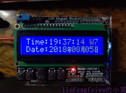
ESP8266+1602时钟(简单版) 2018-8-5
之前做的那些1602时钟虽然使用了DS3231来走时,误差不算太大, 但始终会有点误差。加上上次因为DS3231模块设计问题,导致给纽扣电池的电压达到了5V,最终把电池给弄炸了,威力还不小,让我有点害怕,所以决定做一个基于WiFi自动校时的程序。 上网找了一会,没有现成的方案和代码,但是找到了一个WiFi对时的程序,参见:https://github.com/YFROBOT-TM/YFRobot-NTPClock_OneNet,我的1602时钟也是基于这个WiFi授时改动来的。 硬件连接: 这个版本用的1602是那种带按键的模块式的,直接插上板子即可。 代码: #include <ESP8266WiFi.h> #include <Time.h> #include <Timezone.h> #include "NTP.h" #include <LiquidCrystal.h> // Set your WiFi login credentials #define WIFI_SSID "XXX" // 使用时请修改为当前你的 wifi ssid #define WIFI_PASS "XXX" // 使用时请修改为当前你的 wifi 密码 #define ledPin 14 // 定义ledPin连接到GPIO14 LiquidCrystal lcd(0, 2, 4, 14, 12, 13); //年 byte Nian[8] = {0b01000,0b01111,0b10010, 0b01111, 0b01010, 0b11111, 0b00010, 0b00010}; //月 byte Yue[8] = {0b01111, 0b01001, 0b01111, 0b01001, 0b01111, 0b01001, 0b10011, 0b00001}; //日 byte Ri[8] = {0b01111, 0b01001, 0b01001, 0b01111, 0b01001, 0b01001, 0b01111, 0b00000}; // This clock is in the Mountain Time Zone // Change this for your timezone // 北京时间时区 #define STD_TIMEZONE_OFFSET +8 // Standard Time offset (-7 is mountain time) // *************************************************************** // TimeZone and Daylight Savings Time Rules // *************************************************************** // Define daylight savings time rules for the China TimeChangeRule mySTD = {"", First, Sun, Jan, 0, STD_TIMEZONE_OFFSET * 60}; Timezone myTZ(mySTD, mySTD); WiFiClient client; // This function is called once a second void updateDisplay(void) { TimeChangeRule *tcr; // Pointer to the time change rule // Read the current UTC time from the NTP provider time_t utc = now(); // Convert to local time taking DST into consideration time_t localTime = myTZ.toLocal(utc, &tcr); // Map time to pixel positions int weekdays= weekday(localTime); int days = day(localTime); int months = month(localTime); int years = year(localTime); int seconds = second(localTime); int minutes = minute(localTime); int hours = hour(localTime) ; //12 hour format use : hourFormat12(localTime) isPM()/isAM() Serial.println(""); Serial.print("Current local time:"); Serial.print(days); Serial.print("/"); Serial.print(months); Serial.print("/"); Serial.print(years); Serial.print(" - "); Serial.print(hours); Serial.print(":"); Serial.print(minutes); Serial.print(":"); Serial.print(seconds); Serial.print(" - "); Serial.print(dayStr(weekdays)); Serial.println(""); lcd.clear(); lcd.setCursor(0,0); lcd.print("Time:"); if(hours<10) { lcd.print("0"); } lcd.print(hours); lcd.print(":"); if(minutes<10) { lcd.print("0"); } lcd.print(minutes); lcd.print(":"); if(seconds<10) { lcd.print("0"); } lcd.print(seconds); lcd.print(" W"); printWeek(weekdays); lcd.setCursor(0,1); lcd.print("Date:"); lcd.print(years); lcd.write(byte(0)); if(months<10) { lcd.print("0"); } lcd.print(months); lcd.write(byte(1)); if(days<10) { lcd.print("0"); } lcd.print(days); lcd.write(byte(2)); } void setup() { Serial.begin(115200); pinMode(ledPin, OUTPUT); delay(10); lcd.begin(16, 2); lcd.createChar(0, Nian); lcd.createChar(1, Yue); lcd.createChar(2, Ri); // We start by connecting to a WiFi network initNTP(WIFI_SSID, WIFI_PASS); } // Previous seconds value time_t previousSecond = 0; void loop() { // Update the display only if time has changed if (timeStatus() != timeNotSet) { if (second() != previousSecond) { previousSecond = second(); // Update the display updateDisplay(); } } delay(1000); } void printWeek(int week) { switch(week) { case 1: lcd.print("7");break; case 2: lcd.print("1");break; case 3: lcd.print("2");break; case 4: lcd.print("3");break; case 5: lcd.print("4");break; case 6: lcd.print("5");break; case 7: lcd.print("6");break; default: lcd.print("E");break; } } NTP.h 文件: #ifndef NTP_H #define NTP_H #include <Arduino.h> #include <ESP8266WiFi.h> #include <TimeLib.h> #include <WiFiUdp.h> #define LOCALPORT 5000 // Local port to listen for UDP packets #define NTP_PACKET_SIZE 48 // NTP time stamp is in the first 48 bytes of the message // A UDP instance to let us send and receive packets over UDP WiFiUDP udp; byte packetBuffer[NTP_PACKET_SIZE]; // Buffer to hold incoming and outgoing packets // Don't hardwire the IP address or we won't get the benefits of the time server pool. const char *ntpServerName ;//= "time.windows.com";//"1.cn.pool.ntp.org"; IPAddress timeServerIP(182,92,12,11); //ONENET -- NTP // Send an NTP request to the time server at the given address unsigned long sendNTPpacket(IPAddress& address) { // Set all bytes in the buffer to 0 memset(packetBuffer, 0, NTP_PACKET_SIZE); // Initialize values needed to form NTP request packetBuffer[0] = 0b11100011; // LI, Version, Mode packetBuffer[1] = 0; // Stratum, or type of clock packetBuffer[2] = 6; // Polling Interval packetBuffer[3] = 0xEC; // Peer Clock Precision // 8 bytes of zero for Root Delay & Root Dispersion packetBuffer[12] = 49; packetBuffer[13] = 0x4E; packetBuffer[14] = 49; packetBuffer[15] = 52; // All NTP fields have been given values, now // you can send a packet requesting a timestamp: udp.beginPacket(address, 123); // NTP requests are to port 123 udp.write(packetBuffer, NTP_PACKET_SIZE); udp.endPacket(); } // NTP Time Provider Code time_t getNTPTime() { int attempts = 10; // Try multiple attempts to return the NTP time while (attempts--) { // Get a server from the pool if(ntpServerName != NULL){ WiFi.hostByName(ntpServerName, timeServerIP); } Serial.printf("Time server IP address: "); Serial.println(timeServerIP); while (udp.parsePacket() > 0); // Discard any previously received packets Serial.println("Transmitted NTP Request"); sendNTPpacket(timeServerIP); uint32_t beginWait = millis(); while (millis() - beginWait < 1500) { int size = udp.parsePacket(); if (size >= NTP_PACKET_SIZE) { Serial.println("Received NTP Response"); udp.read(packetBuffer, NTP_PACKET_SIZE); // Read packet into the buffer unsigned long secsSince1900; // Convert four bytes starting at location 40 to a long integer secsSince1900 = (unsigned long) packetBuffer[40] << 24; secsSince1900 |= (unsigned long) packetBuffer[41] << 16; secsSince1900 |= (unsigned long) packetBuffer[42] << 8; secsSince1900 |= (unsigned long) packetBuffer[43]; Serial.println("Got the time"); return secsSince1900 - 2208988800UL; } delay(10); } Serial.println("Retrying NTP request"); delay(4000); } Serial.println("No NTP Response"); return 0; } // Login to WiFi network and assign the time sync provider void initNTP(const char *ssid, const char *password) { // Set station mode WiFi.mode(WIFI_STA); //set work mode: WIFI_AP /WIFI_STA /WIFI_AP_STA // Start by connecting to a WiFi network WiFi.begin(ssid, password); int i = 0; while ((WiFi.status() != WL_CONNECTED) && (i++ < 30)) { delay(500); Serial.printf("."); } if (i == 31) { Serial.printf("\nCould not connect to: %s\n", ssid); return; } Serial.printf("\nConnected to: %s\n", ssid); delay(500); // Login suceeded so set UDP local port udp.begin(LOCALPORT); // Set the time provider to NTP setSyncProvider(getNTPTime); } #endif 效果图: WiFi用到的库文件: https://github.com/PaulStoffregen/Time https://github.com/JChristensen/Timezone
-
自建KMS服务器 2018-7-22
注意:本文所提供的方法仅供测试使用,切勿进行盗版等非法活动! 有时候要激活下系统啥的(仅限VL版),使用第三方的KMS激活软件 有时会不好使,还容易被捆绑一些恶意软件,所以这次自己在NEO上搭建一个激活服务。 登录NEO,查看下系统位数和CPU类型: 查看cpu信息 cat /proc/cpuinfo 查看系统位数 file /bin/ls 当然了,NEO的话这步可以跳过了,主要是在别的机器上要查看下,不然不知道用什么文件。 接着下载软件包: wget https://github.com/Wind4/vlmcsd/releases/download/svn1112/binaries.tar.gz 解压文件,根据CPU类型,找到对应的版本,NEO的是使用的binaries/Linux/arm/little-endian/vlmcsd-armv7el-uclibc-static这个文件。 cd切换到此目录,执行./vlmcsd-armv7el-uclibc-static就可以运行了。 要开机启动,在/etc/rc.local中加入cd /文件所在目录 && ./vlmcsd-armv7el-uclibc-static & 即可。 此服务占用1688端口,注意不要重复。 最后在需要激活的机器上使用以下脚本:http://blog.readgroup.cn/filetool/a/KMS.bat 将脚本中的服务器地址改为自己的即可。