-
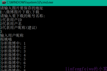
安利一个下载微博用户全部图片的软件weiboPicDownloader 2019-10-13
无意中搜到的,源代码已经超过一年没有更新了,但测试了下还能用,效果不错,速度也可以。 首先下载:https://github.com/yAnXImIN/weiboPicDownloader,找到/bin/wb.jar,下载这个文件就行了。 然后在这个文件的文件夹下新建txt,填入: @echo off "C:\Program Files\Java\jre1.8.0_131\bin\java.exe" -Xms900M -Xmx900M -jar wb.jar pause 然后保存,重命名为.bat。要用的时候直接双击就行了。 使用这个方法不用像原作者那样要配置Java环境,直接安装普通的Java就行了,把Java路径换一下就行了。 使用上依次输入保存路径,选择账号识别方式,输入对应账号识别方式内容,就可以开始下载了。
-

如何制作一个微信公众号的展示logo 2019-9-4
效果如上图啦。纯粹好玩,比那些套用的引导关注样式显得有逼格一点。 01 准备工具:Adobe AE,狸窝全能转换器,视频转GIF软件。 02 现在可以上网找喜欢的AE展示模板了,一搜一大堆。 然后就是修修改改,先把视频做出来。(AE不会用?那不在今天的教学之列啊~~) 这里做的时候要注意,尽量把logo限制在中间的位置,因为下一步会裁剪,原片的比例放上去会不太好看。 渲染的时候可以直接选AVI格式,不过这样出来的体积比较大,然后再用狸窝全能转换器压缩成MP4格式的。 03 经过上一步已经得到了视频文件,下面就是使用gif转换器转换成gif就大功告成了。 选择打开刚刚输出的视频,设置好起点和截止点。尺寸选自定义,分辨率改为640*220,每秒帧数量选1/2,要求不高的可以再降低点。图片颜色选128或256,看最终gif的体积适当调整,整体要控制在2M以下比较好。 最后点击生成即可。
-

利用onedrive和oneindex搭建个人网盘 2019-7-20
利用这套组合搭建的网盘有一个好处就是无需流量,任意分享下载使用。 首先要有一个onedrive账号,直接用微软账号登录即可,一般账号有15G空间,基本也能用了。使用学生版的话最多能得到5T的容量,这可比现有的网盘大多了。不过来源渠道不可靠,能不能保住账号未知,哈哈。反正我自己是不敢用网上那些乱七八糟的子账号的。用了学校的教育邮箱账号,获得了1T的容量,也够用了,有保障。申请学生版地址:https://signup.microsoft.com/signup?sku=student。 接着需要用到oneindex了,一个开源的对接onedrive的php程序。下载:https://github.com/donwa/oneindex。直接解压到服务器使用即可,无需数据库,简单配置下就行。具体使用说明参见它的git页面。另外还找到个相似的:https://github.com/WangNingkai/OLAINDEX,还没试,功能上差不多。 管理这个空间也很简单,下载这个:https://www.raidrive.com/。就可以把onedrive当成一个本地的网络硬盘了,上传删除都和在本地硬盘一样,比较方便。
-

centos 6安装使用aria2 2019-7-13
最近下载github上的大文件越来越困难了,使用酸酸都有点不太行了。正好有台外网的服务器,安装个aria2试下,结果表明下载飞快,然后再下到本地来就ok了。之前在NanoPiNEO上也安装过。(见:http://blog.readgroup.cn/post/63) 系统环境:centos 6 X86 首先安装aira2: 还是使用一键脚本,方面快捷,免折腾: wget -N --no-check-certificate https://raw.githubusercontent.com/ToyoDAdoubi/doubi/master/aria2.sh chmod +x aria2.sh bash aria2.sh 执行了进入安装界面: 0. 升级脚本 ———————————— 1. 安装 Aria2 2. 卸载 Aria2 ———————————— 3. 启动 Aria2 4. 停止 Aria2 5. 重启 Aria2 ———————————— 6. 修改 配置文件 7. 查看 日志信息 ———————————— 当前状态: 未安装 请输入数字 [0-7]: 选择1进行安装,重复执行脚本可以进行升级和修改配置操作。首先要修改存储目录,方便后面使用网页下载。然后要修改令牌,最后加入种子服务器,选择自动更新即可。要是不想上传,把上传速度改为1KB即可。 操作指令: 启动:service aria2 start 停止:service aria2 stop 重启:service aria2 restart 查看状态:service aria2 status 配置文件:/root/.aria2/aria2.conf 至此aira2就可以用了。下面就是还需要安装一个网页环境,之前用的webui,后来又发现了一个更好看的:https://github.com/mayswind/AriaNg,选择下载最新的就行了,解压即用,都可以不上传服务器,直接本地用。不过我这为了后面方便,还是挂在了服务器上。基本操作和别的类似的没啥大区别。然后再使用老牌的文件管理工具:https://kodcloud.com/download/,用来下载和删除文件,这样就不用使用FTP传输了。 参考链接:https://www.zrj96.com/post-420.html
-

phpems使用体验 2019-7-13
因为需要自己练习一些题目,老盯着题目看总没有做题的感觉好,所以就找了一个题库程序。试用了下还可以,基本满足了要求。下载:http://www.phpems.net/。 根据需要选择合适的版本就行了,我就选了普通版。 本来一个软件是不用写一篇博客的,奈何它的说明文档不清楚,上传题库出了点问题,所以还是要自己记录下,以免后面使用的时候忘了。主要是题库导入的模板,按照官方示例根本不行啊。 正确的见下方: 说明: 添加顺序:先再科目管理里面增加至知识点,记住ID,后面要用。再进试卷列表,进行组卷。最后再进入考试设计增加考场。 题型:1为单选,2为多选,3为判断;题干、选项正常填;选项数量根据实际填,不然会出现无法选择正确答案的现象。答案直接填。解析直接填。所属知识点根据系统内设的来对应。难度选1为易,是否题冒题选0。是否题冒选0。注意最好把英文“,”都改为中文“,”,不然在转为CSV时会判断有误,导致格式错乱。还有分列的时候一定要把单元格格式改成文本。按照这个来基本不会错了。 几个常用公式: 计算非空单元格数量:=COUNTA(E2:N2) 合并单元格:=CONCAT(E2:M2) 本站演示站点:http://kaoshi.readgroup.cn/。自用的,涉及行业题目,就不开放了哈。 图片封面分辨率:178*269
-
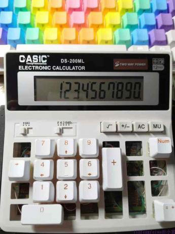
计算器改茶轴实录 2019-7-7
为啥会想到改计算器按键呢?因为原来的按键实在是不好按,怎么都没有机械键盘来的舒服。在网上找了一圈,没有卖这种计算器的存在。倒是有一个很火的青轴的,但青轴比赛的话按着太累,而且只有8位数,按键排列也不舒服,根本没法比赛用。所以就只能给自己打造一个了。 材料很简单,一些茶轴加导线即可。 首先拆开计算器,分析了下电路板上的矩阵排列,把路线和轴重复的地方先焊接好,再一一对应接好即可。看着简单,实际接起来还挺费事的。 本来想保留一些原有的功能的,但拆了之后原来的按键都不能用了,所以最终放弃了,需要用到的键都改了,包括开机键。最终就呈现了一个专门用来百张传票翻打的计算器。 下一步的目标就是开发一个专门的银行专用的计算器,在DL-2135的基础上把按键都改为茶轴,数字部分保持和电脑同步,这样就不用去互相适应了,其余不变。再增加一个模式,用来一键屏蔽掉不需要的按键,这样比赛的时候就不用扣按键了,哈哈。希望这个产品最终能够面世吧。
-
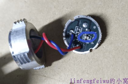
强光手电三档改一档 2019-2-25
之前在网上买的那种用18650电池的强光手电,便宜好用,但有一点烦人的是它有三个挡。分别是强、弱、爆闪。每次开机都是上次用过的档位下一挡,很烦。然后就拆开看了下,结构很简单,起控制作用的 就一个三极管加一个电容,问题就在这个电容上。 只需把它拆掉,就可以让它不再具有这种烦人的记忆功能,每次打开就能保持上次关闭时的状态了。目前还是能够调节三种模式的,不过方法要变,每次开机之前长按按键停留一会就能变成下一个模式。 新增:还是受不了带档位的了,直接把那个三极管也扣了,只留下那几个限流电阻,开关只控制开关,完美了。
-
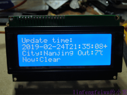
esp8266+lcd2004打造迷你天气预报 2019-2-24
一个很简单的天气显示系统,采用lcd2004作为显示器,能够显示当前联网获得的天气,配合之前室内的那个温度来用,绝配啊。 连线很简单,只需将2004按IIC方式连接在esp8266上即可。 代码: #include <ESP8266WiFi.h> #include <ArduinoJson.h> #include <Wire.h> //GPIO4(SDA) GPIO5(SCL) //I2C LCD: #include <Wire.h> // Comes with Arduino IDE #include <LiquidCrystal_I2C_DS3231.h> // Set the LCD I2C address #define I2C_ADDR 0x27 // Define I2C Address for the PCF8574T //---(Following are the PCF8574 pin assignments to LCD connections )---- // This are different than earlier/different I2C LCD displays #define Rs_pin 0 #define Rw_pin 1 #define En_pin 2 #define BACKLIGHT_PIN 3 #define D4_pin 4 #define D5_pin 5 #define D6_pin 6 #define D7_pin 7 #define LED_OFF 0 #define LED_ON 1 /*-----( Declare objects )-----*/ LiquidCrystal_I2C lcd(I2C_ADDR,En_pin,Rw_pin,Rs_pin,D4_pin,D5_pin,D6_pin,D7_pin); #define ledPin 14 // 定义ledPin连接到GPIO14 //年 byte Nian[8] = {0b01000,0b01111,0b10010, 0b01111, 0b01010, 0b11111, 0b00010, 0b00010}; //月 byte Yue[8] = {0b01111, 0b01001, 0b01111, 0b01001, 0b01111, 0b01001, 0b10011, 0b00001}; //日 byte Ri[8] = {0b01111, 0b01001, 0b01001, 0b01111, 0b01001, 0b01001, 0b01111, 0b00000}; //摄氏度 byte du[8] = {0b11000,0b11011,0b00100, 0b00100, 0b00100, 0b00100, 0b00011, 0b00000}; const char* ssid = " XXXXXX"; // XXXXXX -- 使用时请修改为当前你的 wifi ssid const char* password = " XXXXXX"; // XXXXXX -- 使用时请修改为当前你的 wifi 密码 const char* host = "api.seniverse.com"; const char* APIKEY = "wcmquevztdy1jpca"; //API KEY const char* city = "nanjing"; const char* language = "en";//zh-Hans 简体中文 会显示乱码 const unsigned long BAUD_RATE = 115200; // serial connection speed const unsigned long HTTP_TIMEOUT = 5000; // max respone time from server const size_t MAX_CONTENT_SIZE = 1000; // max size of the HTTP response // 我们要从此网页中提取的数据的类型 struct UserData { char city[16];//城市名称 char weather[32];//天气介绍(多云...) char temp[16];//温度 char udate[32];//更新时间 }; WiFiClient client; char response[MAX_CONTENT_SIZE]; char endOfHeaders[] = "\r\n\r\n"; /** * @Desc 初始化操作 */ void setup() { lcd.begin(20, 4); // Switch on the backlight lcd.setBacklightPin(BACKLIGHT_PIN,POSITIVE); lcd.setBacklight(LED_ON); lcd.createChar(0, Nian); lcd.createChar(1, Yue); lcd.createChar(2, Ri); lcd.createChar(3, du); WiFi.mode(WIFI_STA); //设置esp8266 工作模式 Serial.begin(BAUD_RATE); delay(10); Serial.println(); Serial.println(); Serial.print("Connecting to ");//写几句提示,哈哈 Serial.println(ssid); WiFi.begin(ssid, password); //连接wifi while (WiFi.status() != WL_CONNECTED) { //这个函数是wifi连接状态,返回wifi链接状态 delay(100); Serial.print("."); } Serial.println(""); Serial.println("WiFi connected"); delay(100); Serial.println("IP address: "); Serial.println(WiFi.localIP());//WiFi.localIP()返回8266获得的ip地址 client.setTimeout(HTTP_TIMEOUT); } /** * @Desc 主函数 */ void loop() { while (!client.connected()){ if (!client.connect(host, 80)){ Serial.println("connection...."); delay(100); } } if (sendRequest(host, city, APIKEY) && skipResponseHeaders()) { clrEsp8266ResponseBuffer(); readReponseContent(response, sizeof(response)); UserData userData; if (parseUserData(response, &userData)) { printUserData(&userData); } } delay(300);//每5s调用一次 } /** * @发送请求指令 */ bool sendRequest(const char* host, const char* cityid, const char* apiKey) { // We now create a URI for the request //心知天气 String GetUrl = "/v3/weather/now.json?key="; GetUrl += apiKey; GetUrl += "&location="; GetUrl += city; GetUrl += "&language="; GetUrl += language; // This will send the request to the server client.print(String("GET ") + GetUrl + " HTTP/1.1\r\n" + "Host: " + host + "\r\n" + "Connection: close\r\n\r\n"); Serial.println("create a request:"); Serial.println(String("GET ") + GetUrl + " HTTP/1.1\r\n" + "Host: " + host + "\r\n" + "Connection: close\r\n"); delay(100); return true; } /** * @Desc 跳过 HTTP 头,使我们在响应正文的开头 */ bool skipResponseHeaders() { // HTTP headers end with an empty line bool ok = client.find(endOfHeaders); if (!ok) { Serial.println("No response or invalid response!"); } return ok; } /** * @Desc 从HTTP服务器响应中读取正文 */ void readReponseContent(char* content, size_t maxSize) { size_t length = client.peekBytes(content, maxSize); delay(100); Serial.println("Get the data from Internet!"); content[length] = 0; Serial.println(content); Serial.println("Read data Over!"); client.flush();//这句代码需要加上 不然会发现每隔一次client.find会失败 } /** * @Desc 解析数据 * 数据格式如下: * { * "results": [ * { * "location": { * "id": "WX4FBXXFKE4F", * "name": "北京", * "country": "CN", * "path": "北京,北京,中国", * "timezone": "Asia/Shanghai", * "timezone_offset": "+08:00" * }, * "now": { * "text": "多云", * "code": "4", * "temperature": "23" * }, * "last_update": "2017-09-13T09:51:00+08:00" * } * ] *} */ bool parseUserData(char* content, struct UserData* userData) { // -- 根据我们需要解析的数据来计算JSON缓冲区最佳大小 // 如果你使用StaticJsonBuffer时才需要 // const size_t BUFFER_SIZE = 1024; // 在堆栈上分配一个临时内存池 // StaticJsonBuffer<BUFFER_SIZE> jsonBuffer; // -- 如果堆栈的内存池太大,使用 DynamicJsonBuffer jsonBuffer 代替 DynamicJsonBuffer jsonBuffer; JsonObject& root = jsonBuffer.parseObject(content); if (!root.success()) { Serial.println("JSON parsing failed!"); return false; } //复制我们感兴趣的字符串 strcpy(userData->city, root["results"][0]["location"]["name"]); strcpy(userData->weather, root["results"][0]["now"]["text"]); strcpy(userData->temp, root["results"][0]["now"]["temperature"]); strcpy(userData->udate, root["results"][0]["last_update"]); // -- 这不是强制复制,你可以使用指针,因为他们是指向“内容”缓冲区内,所以你需要确保 // 当你读取字符串时它仍在内存中 return true; } // 打印从JSON中提取的数据 void printUserData( struct UserData* userData) { Serial.println("Print parsed data :"); lcd.clear(); lcd.setCursor(0,0); lcd.print("Update time:"); lcd.setCursor(0,1); lcd.print(userData->udate); lcd.setCursor(0,2); lcd.print("City:"); lcd.print(userData->city); lcd.print(" Out:"); lcd.print(userData->temp); lcd.write(byte(3)); lcd.setCursor(0,3); lcd.print("Now:"); lcd.print(userData->weather); delay(4*1000); } // 关闭与HTTP服务器连接 void stopConnect() { Serial.println("Disconnect"); client.stop(); } void clrEsp8266ResponseBuffer(void){ memset(response, 0, MAX_CONTENT_SIZE); //清空 } lcd2004的使用基本参照1602来,库也是一样的,只要改变下显示位置就行了。获取网络天气的代码来自:http://bbs.doit.am/forum.php?mod=viewthread&tid=442&extra=。没有自己去申请api,直接用了原作者的。哪一天失效了再自己改吧。 成品图:
-

esp8266通过USB转ttl烧写方法 2019-2-23
因为usb接口坏了,所以需要直接使用GPIO接口来烧录程序。 别的没啥要注意的,主要把GPIO0口接地就行了。别的按照usb模块来接就行了。
-

OSU键盘小幅度升级 2019-1-7
之前的那个键盘因为用的鼠标主控(见http://blog.readgroup.cn/post/40),会和数位板产生冲突,禁掉鼠标按键的话使用上又不方便,所以就还是换键盘的主控吧。本来想用digispark做主控的,但是延迟啥的没处理好,这个方案以后再说吧。目前用digispark来控制LED呼吸灯。 成品如图: 接口上也改为了microusb接口,更加方便携带。所有焊接处都用热熔胶封死,不小心漏了,导致有点多了。 键盘主控如图: 只焊接了ZX两个按键,打OSU足够了。